
Rail Systems
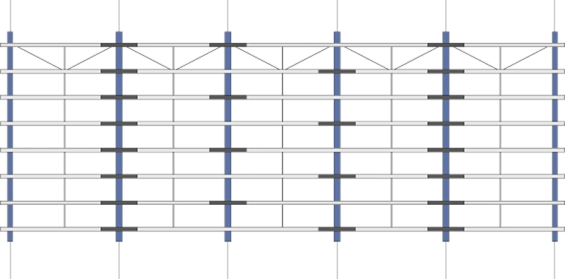
The section depth of the rail plus the clearance required for a standard fixing cleat determine the minimum dimension from the column face to the inside of the vertical cladding. Joints in the rails are sleeved to give continuity, allowing the use of more economical sections and giving an improved deflection performance.
Double Span Joint Arrangement
This system combines single and double span rails with their joints staggered and sleeved. The provision of a sleeve at the unjointed connections over the penultimate support is required.
Non Standard Punching Patterns
Additional holes on the standard punchlines will be made as detailed. Non standard punchlines can be incorporated at no extra charge.
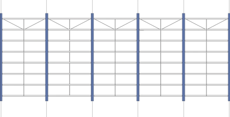
As the rails are single spans simply supported between the columns, they can be positioned to suit the architectural details, rather than be governed by the section depth of continuous rail systems that must pass across the column faces. Note: Where damage to the finishes might arise from the effects of deflection in side rails, or where rails are intended to provide lateral restraint to the tops of brick walls, deflection design checks should be carried out, with use of our design suite.
Butted Joint Arrangement
This system can occasionally involve notched end connections to the rails due to width restrictions imposed by the Architect. Non standard cleats are therefore required.
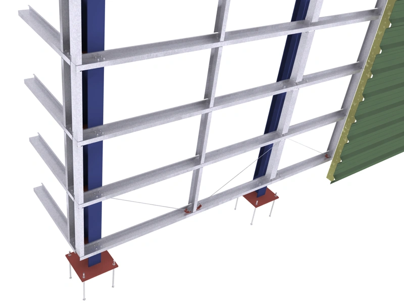
Vertical Cladding Rails
The Vertical Cladding Rail section used in conjunction with the Window Channel Pressing provide a suitable solution to the increasing need for horizontal cladding support.
Our VCR has a larger 140mm fixing face to accommodate two panels at joint positions. These joints usually occur at column positions, where the VCR can be fixed directly to the column using hot rolled cleats. These are also used when the joint line falls within the span.
Window Channel Pressings
The Window Channel Pressing has been introduced to provide an economic alternative to the vertical channel sections with cleats.
Our WCP is used to trim window openings, and also as an intermediate fixing face where vertical members have to remain within the rail zone for architects' requirements.
WCP's auto formed ends removes the need for on-site assembly of cleats. The section also utilises a thicker material gauge, therefore removing the need for lips.
Maximum Span
WCP and VCR section sizes have been designed to suit the standard 1.8m rail centres. They have the capacity to span up to 2.0m but beyond this we recommend you consult our Technical Department.
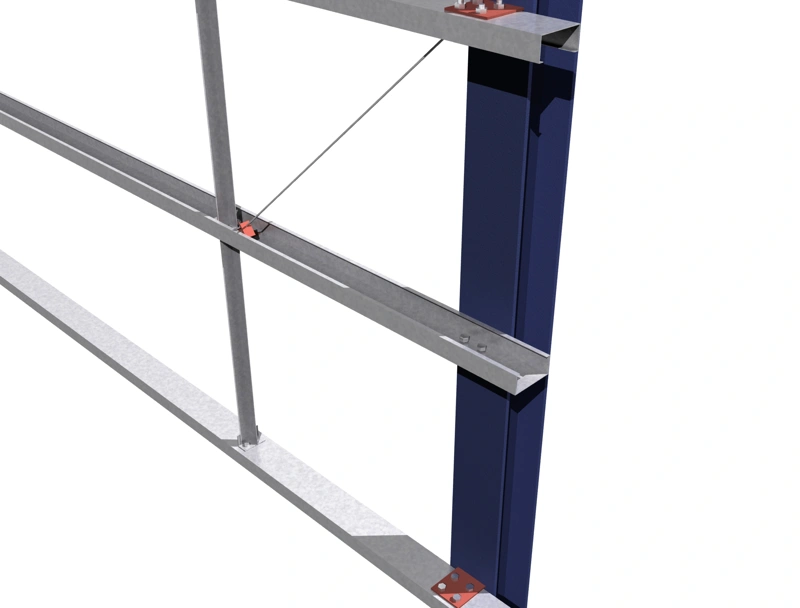
These are necessary to ensure that the rails line level along the length of the building and also provide torsional restraint to the unrestrained flange.
The system consists of a continuous line of struts at either mid, third or quarter points along the rail span. In order to support the rails against vertical deflection diagonal tie wires are required. Where a hot rolled structural members of adequate strength is used as an eaves beam, the anti-sag system can be suspended from it therefore removing the necessity of the wires.
Rigid Fix Struts
Rigid-fix struts are manufactured from 2.0mm pre-galvanised material, which is riveted either end to ST cleats. The angle member has the capacity to resist compressive forces that may occur.
Diagonal Bracing
Diagonal braces are manufactured from seven separate strands of wire rope with an adjustable threaded end, and a fixed 'ball type' end swaged to the wires. For all rail systems diagonal braces are required to support the rails against sagging under their own self-weight about the minor axis. Where struts can be fixed back to an adequate hot rolled eaves member, the diagonal braces are not required.
With a strut anti-sag system the diagonals can be placed anywhere in the bay, but we recommend between the bottom lines as this will aid erection.
Additional sets of diagonal braces are needed according to the meterage of cladding they must support. As a rule each set can support up to 10m of metal cladding or 7.5m of fibre cement sheeting. After this further braces are required. (As an alternative to the wire rope brace system, we can also offer a tubular diagonal brace system).
The bracing bracket fixed to the cleat attached to the column must use the holes closest to the column, whereas the bracket that fixes to the centre of the rail should fix to the outer holes closest to the cladding.
Additional Diagonals
Further sets of diagonal wires are required at the following dimensions. Dim H = 10m for metal cladding and 7.5m for fibre cement cladding.